Overview
This section describes how devices can interact with Cloud of Things over the Narrowband IoT (NB-IoT) network using the MQTT-SN (MQTT For Sensor Networks) protocol via the NB-IoT Connector.
User’s equipment is able to send measurements, alarms, and events via MQTT-SN messages. The NB-IoT Connector processes the incoming MQTT-SN messages through the MQTT-SN-Gateway and passes them to Cloud of Things.
Important: The MQTT-SN protocol has been provided for Cloud of Things via a MQTT-SN Gateway (NB-IoT Connector) as a proposition for early adopters to test the Narrowband IoT network. The use of the MQTT-SN protocol via the NB-IoT Connector is no longer recommended for new implementations. Please consider using the OMA LightweightM2M (LwM2M) protocol for new implementations instead.
Device Management
To gain access to NB-IoT via MQTT-SN the following materials and information are provided and required:
- SIM card with unique IMSI (International Mobile Subscriber Identity)
- Associated password to each IMSI number (user-defined)
- Cloud of Things credentials for web interface
Each device, respectively SIM card needs to be preregistered to Cloud of Things prior to using. The preregistration is accomplished by uploading a csv file, comprising the device data onto Cloud of Things. The format of the CSV file and the uploading steps are described in the Cloud of Things User Guide in Chapter “Device Management”.
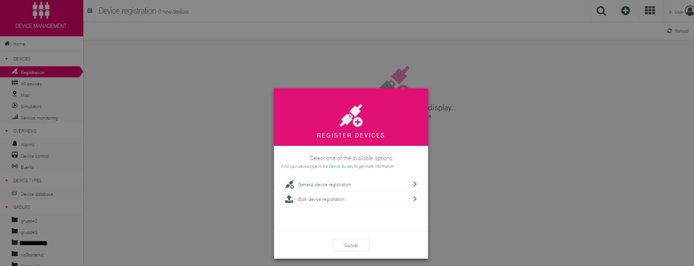
Registering devices
To register your devices, you can upload a CSV file with the IDs and credentials. When uploading the CSV file, Cloud of Things creates user accounts for each device listed in the file. It ensures that devices can connect securely to Cloud of Things without the need to do a manual device registration.
The CSV file needs to have a header row with categories followed by the actual data in the same logic and sequence as defined in the header. You can either create the CSV file by yourself, or alternatively put the data into an Excel file and save it in CSV format. This will convert the data into the proper form.
Bulk upload for NB-IoT devices:
The headlines for the CSV file are ID, Credentials, Type, Name, ICCID, Shell, com_Cloud of Things_model_Agent,c8y_Mobile.imsi, c8y_Mobile.imei.
The columns are used as follows:
ID: ID of the device as referencing within Cloud of Things (always IMSI for NB-IoT)Credentials: Password that is used by the device for the registration in Cloud of Things (user-defined, have to be of 8 letters and UTF-8 conform).Type: Type of the device. If the device should be connected via MQTT-SN, the typenbiothas to be registered.Name: Name of the device for the display within the device management.ICCID: Is used as the device’s registration name for Cloud of Things.Shell: Is a flag (0or1) whether to allow the sending of operations to a device or not (1=yes).Com_cumulocity_model_Agent: necessary to display the device within the inventory. The curly brackets are empty{}.C8y_Mobile.imsi: IMSI that is assigned to your SIM card. You get the information with your SIM cards.C8y_Mobile.imei: IMEI of the device.
An appropriate example could look like this:
ID;CREDENTIALS;TYPE;NAME;ICCID;SHELL;com_cumulocity_model_Agent;c8y_Mobile.imsi;c8y_Mobile.imei
123456789123456;LF2PWJOL;nbiot;Device1;123456789123456;;;1;{};123456789123456;987654321098765
In the file each device needs to be listed in a separate line.
After the upload, the corresponding device access is created in the Cloud of Things with the specified passwords on the tenant and the connector.
Note: After the upload of the CSV in some cases it can take up to 10 minutes until the connection is successful.
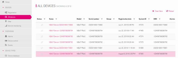
Overview of devices
The overview of preregistered and registered devices can be shown in the web interface of the Cloud of Things in the
“Device Management” app via the menu entry “Devices” → “All devices” → NB-IoT Device
Preregistered SIM cards are in status “pending” in the “Registration” view. The registration is finished right after the devices successfully connected via MQTT-SN for the first time. If that was the case, the device will then be visible under “All devices” view.
Connecting to MQTT-SN gateway
The combination of IMSI and authentication key (password) results in ClientID. The ClientID is used for the authentication of the devices to the MQTT-SN gateway (NB-IoT Connector).
In order to ensure the uniqueness of a device, a key for authentication is provided to each device. The authentication key can be placed at the disposal.
The MQTT-SN CONNECT is used for the authentication. Please refer to the MQTT-SN specification, section 5.4.4 “Connect”. The CONNECT
message contains the ClientID. The ClientID is a 23-character long
string, which uniquely identifies the client in a server. The string
of the ClientID consists of the IMSI and the assigned password. The
IMSI consists of 15 characters. The remaining 8 characters of the
ClientID are used for the password.
An example of the combination of the ClientID is:
- IMSI:
123456789012345 - Password:
SRUkRd5H - ClientID:
123456789012345SRUkRd5H
Identification of IMSI
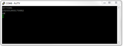
AT commands are instructions used to control a modem. The AT+CIMI
command queries the IMSI, a 15-digit unique identifier of the SIM
card. Please have a look at your modem manual to assert your console
interface. Users of the Prototyping Hub are able to use the console
interface of PSoC2 (Programmable System on Chip). The operation
response is shown in the image below.
Deleting Devices
To delete a device, go to the device overview in “Device Management” app by choosing “All devices", select the device you want to delete, click “Delete” shown as a red cross on the very right and confirm your choice.
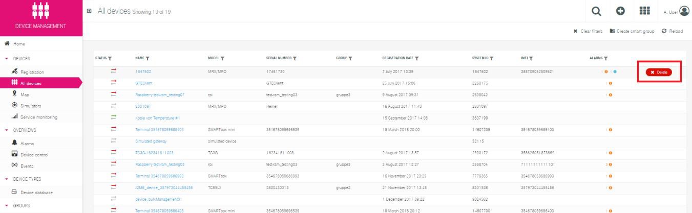
Important: Please note that deleting a device means removing the device from the device list with all its data. If you want to completely delete the device from the platform database, you need to delete the device credentials as well. This is especially relevant if you want to re-register the device in the Cloud of Things.
Alternatively, you can “deactivate” devices without deleting data. This function is useful when you e.g. want to check if a particular device type is causing an error by temporarily ending the communication.
To delete the credentials, go to the “Device Management” app, find a “Management” folder in the navigation menu on the left-hand side, and choose “Device Credentials". Delete the gateway from the list.
Cloud of Things
This section describes the different types of Cloud of Things specific messages and their content.
Viewing Data via Cloud of Things GUI
In the following chapters the relevant views of the Cloud of Things web portal are explained.
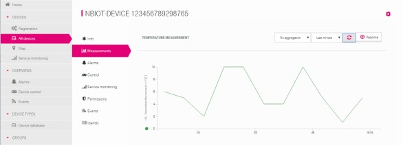
Device Data View
All transmitted device data can be viewed via Cloud of Things web interface under “Device Management” app, via the menu entry “Devices” → “All devices” → Device (in format: NB-IoT Device + IMSI) → Measurements. The image below depicts the temperature profile of the “NBIOT-DEVICE 123456789298765”.
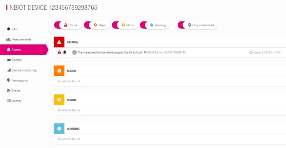
Alarm View
Via the menu entry “Devices” → “All devices” → Device (in format: NB-IoT Device + IMSI) → Alarms, the user can view the generated alarms of the device. The image below shows the example of an alarm.
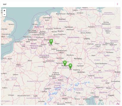
Event View
Via the “Cockpit” app under menu entry “Home” → “Map", the user can view the transmitted position of the device. The image below shows the position of the devices.
MQTT-SN Messages
The general MQTT-SN Specification can be downloaded here.
Structure of MQTT-SN Message Content
The NB-IoT Connector requires a predefined MQTT-SN message content structure for processing the data and connection to Cloud of Things. The MQTT-SN message consists of a topic and the payload.
MQTT-SN Topic Levels
The MQTT-SN topic has a hierarchy of 4 topic levels:
| Topic | Definition |
|---|---|
| NBIoT | NB-IoT root node |
| IMSI | unique device ID (HexString) |
| MessageType | MES (Measurement), ALM (Alarm), EVT ( Event) |
| PayloadID | ID for the payload contents (HexString) |
The general structure of a MQTT-SN topic is:
NBIoT/<IMSI>/< MessageType >/<PayloadID>
Example: NBIoT/123456789298765/MES/471A
NBIoTis the specified root node123456789298765is the unique IMSI numberMESdefines the MessageType “measurement”471A. The PayloadID defines the MQTT-SN payload structure
MQTT-SN Payload
The use and the compilation of the MQTT-SN payload depend on the used MQTT-SN topic. The payload consists of a binary byte array. The supported data types are described in the table below. This table contains the properties of the data type, the size and a sample.
| Data Type | Size in Byte | Example |
|---|---|---|
| boolean | 1 | true (non-zero value) or false (zero value) |
| int8 | 1 | -128 to 127 |
| uint8 | 1 | 0 to 255 |
| short (big endian byte order) | 2 | -32768 to 32767 |
| int32 (big endian byte order) | 4 | −2.147.483.648 to 2.147.483.647 |
| long (big endian byte order) | 8 | −9.223.372.036.854.775.808 to 9.223.372.036.854.775.807 |
| float (big endian byte order) | 4 | 1,2E-38 to 3,4E+38 |
| double (big endian byte order) | 8 | 2,3E-308 to 1,7E+308 |
| date4 (big endian byte order) | 4 | 1472543729 = Unix epoch time (seconds) |
| date8 (big endian byte order) | 8 | 1472543729000 = Unix epoch time (milliseconds) |
| Char | 1 | A |
| string | N | ADCDEF\0 = Zero terminated character array |
Send Measurement
The section “Send Measurement” describes the structure of MQTT-SN message and the supported measurements. The supported measurements are divided into simple and complex structures.
Structure of MQTT-SN Message
The general structure of MQTT-SN message is described in the previous chapter. The structure of the measurement message uses the value “MES” as event type. The topic “MES” is used for all measurement messages. All available measurement topics are described in the table below.
The measurement ID corresponds to a predefined set of measurement values. The correspondence between measurement ID and measurement values is defined in the section “Simple Measurement”.
| Topic | Definition |
|---|---|
| NBIoT | NB-IoT root node |
| IMSI | unique device ID (HexString) |
| MES | Measurement |
| PayloadID | ID for the payload contents (HexString) |
An example for a general measurement structure with the following topic:
NBIoT/123456789298765/MES/1
The size and the use of the payload depend on
the value of the PayloadID. In this example, the PayloadID is 1 and
corresponds to measurement value “Temperature”. The payload of the
“Temperature” measurement type uses a string data type.
Examples:
- 12 Degrees:
12(0x31, 0x32) - -12.5 Degrees:
-12.5(0x2D, 0x31, 0x32, 0x2E, 0x35)
Simple Measurement
A simple measurement message sends exactly one measurement value. In the table below all available measurement types are listed. This table contains the mapping between measurement ID and measurement type, the data type and the measurement unit. The supported measurement types are expandable at any time.
| Measurement Type | Measurement ID | Data Type | Measurement Unit |
|---|---|---|---|
| Temperature | 1 | String | C |
| Voltage | 2 | String | mV |
| Acceleration | 3 | String | m/s2 |
| Light | 4 | String | Lux |
| Humidity | 5 | String | %RH |
| Moisture | 6 | String | % |
| Distance | 7 | String | Mm |
| Current | 8 | String | A |
| SignalStrength | 9 | String | dBm |
| Pressure | A | String | Db |
| Volume | B | String | Sone |
| Weight | C | String | G |
| Frequency | D | String | Hz |
Measurement ID: exadecimal representation
String: String without terminating zero
Complex Measurement
In complex measurement the user has the possibility to send more than one measurement value in one MQTT-SN message. In the following chapters, all available complex measurement types are listed.
Motion
PayloadID: 186A1
| Value | Data Type | Unit | Description |
|---|---|---|---|
| Motion Detected | boolean | Boolean value indicating whether motion has been detected (non-zero value) or not (zero value) | |
| Speed | float | km/h | Measured speed towards (+ve) or away ( -ve) from the sensor. |
Motion Example
An example for a motion measurement topic structure is MQTT-SN topic:
NBIoT/123456789298765/MES/186A1
The payload contains the values:
- motionDetected:
true(0x01) - speed:
-63.2(0xC2, 0x7C, 0xCC, 0xCD)
MQTT-SN payload: 0x01, 0xC2, 0x7C, 0xCC, 0xCD
Single Phase Electricity
PayloadID: 186A2
| Value | Data Type | Unit | Description |
|---|---|---|---|
| A+ | short | kWh | Total active energy, in |
| A- | short | kWh | Total active energy, out |
| P+ | short | W | Total active power, out |
| P- | short | W | Total active power, in |
Send Alarm
In addition to the measurement messages, the NB-IoT Connector supports alarm messages. Each device can trigger an alarm in the Cloud of Things over the MQTT-SN message. The construction and the application of the alarm MQTT-SN message are described in the following chapter.
Structure of MQTT-SN Message
The general structure of MQTT-SN message is described in the chapter “Structure of MQTT-SN Message Content". The structure of the alarm message uses the value “ALM” as event type. The topic “ALM” is used for all alarm messages. The structure of the alarm topic is described in the table below.
| Topic | Definition |
|---|---|
| NBIoT | NB-IoT root node |
| IMSI | unique device ID (HexString) |
| ALM | Alarm |
| Severity ID | Severity Level (1 – 4) |
An example for a general alarm structure is:
NBIoT/123456789298765/ALM/1
The Severity ID supports four levels. These levels are described in chapter “Supported Severity Levels”. The severity ID is a numerical character between 1 and 4.
The alarm MQTT-SN payload is defined as a String.
The MQTT-SN payload contains the alarm message. The MQTT-SN payload is the content of the alarm in the Cloud of Things. An example of an alarm MQTT-SN payload is:
"The measured temperature passes the threshold".
Supported Severity Levels
The alarm message supports four levels of the severity. This levels are Critical, Major, Minor und Warning. The correspondence between severity ID and severity levels is described in the table below.
| Severity ID | Severity Level |
|---|---|
| 1 | Critical |
| 2 | Major |
| 3 | Minor |
| 4 | Warning |
Send Event
In addition to the measurement and alarm messages, the NB-IoT connector supports event messages. Each device can trigger an event in the Cloud of Things over the MQTT-SN message. The construction and the application of the event MQTT-SN message are described in the following chapter. An example for the event message is sending position information.
Structure of MQTT-SN Message
The general structure of MQTT-SN message is described in section Structure of MQTT-SN Message Content. The event message uses the value “EVT” as event type. The topic “EVT” is used for all event messages. The structure of the event topic is described in the table below.
| Topic | Definition |
|---|---|
| NBIoT | NB-IoT root node |
| IMSI | unique device ID (HexString) |
| EVT | Event |
| EventID | ID for associating the event of the payload (HexString) |
In the next sections, the supported types of events are described.
Position (Altitude, Latitude, Longitude) with Message
EventID: 1
| Value | Data Type | Unit | Description |
|---|---|---|---|
| Alt | float | M | Altitude |
| Lat | float | degrees | Latitude |
| Long | float | degrees | Longitude |
| Message | String | - | Event Message |
Position (Latitude, Longitude) with Message
EventID: 2
| Value | Data Type | Unit | Description |
|---|---|---|---|
| Lat | float | degrees | Latitude |
| Long | float | degrees | Longitude |
| Message | String | - | Event Message |
Position (Latitude, Longitude)
EventID: 3
| Value | Data Type | Unit | Description |
|---|---|---|---|
| Lat | float | degrees | Latitude |
| Long | float | degrees | Longitude |
The Event Message is predefined and is “Location Update”.
Position Example
An example for an event position structure is MQTT-SN topic:
NBIoT/123456789298765/EVT/3
The payload contains the values:
- Lat:
6.15173(0x40, 0xC4, 0xDA, 0xF9) - Long:
51.211977(0x42, 0x4C, 0xD9, 0x10)
MQTT-SN payload: 0x40, 0xC4, 0xDA, 0xF9, 0x42, 0x4C, 0xD9, 0x10
Downlink Message
Downlink messages are custom messages sent from Cloud of Things to the device. Downlink messages can contain configuration values.
Workflow for Downlink Message
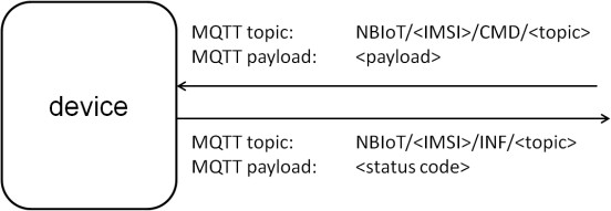
Via the Cloud of Things GUI, the user has the possibility to configure a downlink message for the device. The user can specify a subtopic and the payload of the downlink message. The predefined structure of the downlink message is described in the chapter Structure of Downlink Message. For downlink communication, the MQTT-SN topic structure has 2 subtopics (CMD and INF). The CMD topic is used to send commands to the device (also known as Operations), the INF topic is used for sending command responses from the device. The responses contain status codes which are displayed on the GUI.
 {width="4.549730971128609in”
height="1.5717705599300087in”}
{width="4.549730971128609in”
height="1.5717705599300087in”}
Structure of Downlink Message
On the Cloud of Things GUI, the user must use a predefined input format for commands:
topic:<topic>;data:<payload>
The parameters <topic> and <payload> are freely selectable. The
parameter <topic> is a subtopic of the CMD topic. The parameter
<payload> is the MQTT-SN payload formatted as a hex dump.
In the next step, an example of usage is described.
Scenario: A timer value shall be sent to the device. The commands topic is “SetTimer” and the payload is any time value (formatted as hex dump).
The complete command that must be entered in the Cloud of Thingss GUI is:
topic:SetTimer;data:3132
The device receives the following MQTT-SN message:
- MQTT-SN topic:
NBIoT/<IMSI>/CMD/SetTimer - MQTT-SN payload:
0x31, 0x32
If the message is processed successfully, the device sends the following MQTT-SN message to theCloud of Things:
- MQTT-SN topic:
NBIoT/<IMSI>/INF/SetTimer - MQTT-SN payload:
0x30
Status Codes
The status codes are used to signal the status of the command. The device sends the status code to the Cloud of Things. The Cloud of Things processes the code and visualizes the status on the GUI. The code is a unit8 value. All available status codes are described in the table below.
| Value | Status |
|---|---|
0 (0x30) |
SUCCESFUL |
1 (0x31) |
FAILED |
2 (0x32) |
EXECUTING |
3 (0x33) |
PENDING |
Send Downlink Message – Cloud of Things Interface
This section shows how to send a downlink message with the Cloud of Things GUI. Each device has a sub-menu for sending the download message. You can reach it in “Device Management” app via the menu entry “Device” → “All devices” → single device → “Shell").
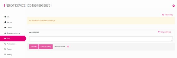
The downlink message is configured via the command text field. The structure of downlink message is defined in section Structure of Downlink Message. After pressing the “Execute” button, the downlink message is sent to the device.

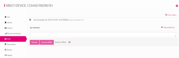
After sending the downlink message, the status of the message is displayed in the Cloud of Things interface. The initial status is pending.

After receiving the message, the device sends a response/acknowledgement to the Cloud of Things. The response contains the status of the downlink message. The Cloud of Things GUI displays this status information. The status can be “SUCCESFULL”, “FAILED”, “EXECUTING” or “PENDING”.
This section described the procedure for sending the downlink message.
Send Bulk Messages to Groups of Devices
The procedure for creating a device groups is described in the following section. Via Cloud of Things GUI:
Create a device group:
- Menu “GROUPS”
- “Add group”-button
- Select a group name
- “Add group”-button
- Add devices:
- Menu “GROUPS”
Created group:
- Menu “Sub-assets”
- “Assign devices”-button
- Select the devices
- “Assign devices”- button
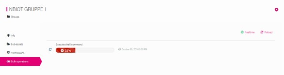
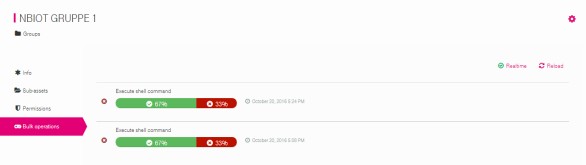
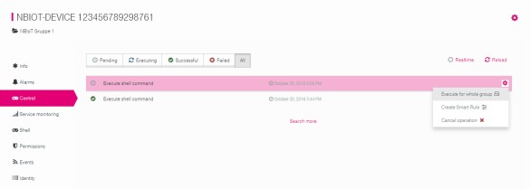
After a device group was created, the bulk messages can be sent to the devices. To send a bulk message, the user sends a single downlink message to any device Send Downlink Message – Cloud of Things Interface. The single downlink message serves as basis for sending the bulk message. Via the menu entry “All devices” → single device → “Control", the usercan start sending the bulk message via the “Execute for whole group"-button.
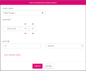
In the next step, the user has the possibility to configure the target group, the start time and the delay between the messages.
After sending the message to the whole group, the status for sending and receiving is accessible via the menu “GROUPS” → device group → “Bulk operations". The GUI displays status changes for the bulk message.